Project Overview
The purpose of this project is to design and build a circuit that will simulate the decision outcomes based on the yes/no votes of a President, Vice President, Secretary, and Treasurer. In the case of a tie, the side with which the President votes will win, because the President breaks the tie. We are doing this project to practice using Multisim and breadboards to create circuits. One constraint is that only 2-input gates can be used.
Problem Conception
Truth Table & Un-Simplified Expression

The purpose of a truth table is to easily and correctly determine the true outputs for a function based on the values of the inputs of each variable. The number of rows in a table is determined by taking the number 2 to the power of the amount of variables being observed. The table shows that in the case of a tie, the final decision is equal to the decision of the President.
In the picture above, the un-simplified logic expression is derived from the truth table, which is in Sum of Products form, in 8 minterms taken from each row of the table in which the function outputs a "1". The SOP form is easier because you can just follow the table across and write down each variable to create each minterm and you do not have to use any Boolean algebra yet.
Un-Simplified Circuit (Multisim)

The un-simplified circuit is in bus form, which makes it more organized and easier to trace the wires. This circuit requires 4 inverter gates, 24 AND gates, and 7 OR gates. This means that to build this circuit, you would need 1 inverter chip, 6 AND chips, and 2 OR chips.
Boolean Algebra Simplification

The simplified Boolean expression is found using Boolean algebra to condense the expression and make it easier to create a circuit.
Simplified Circuit
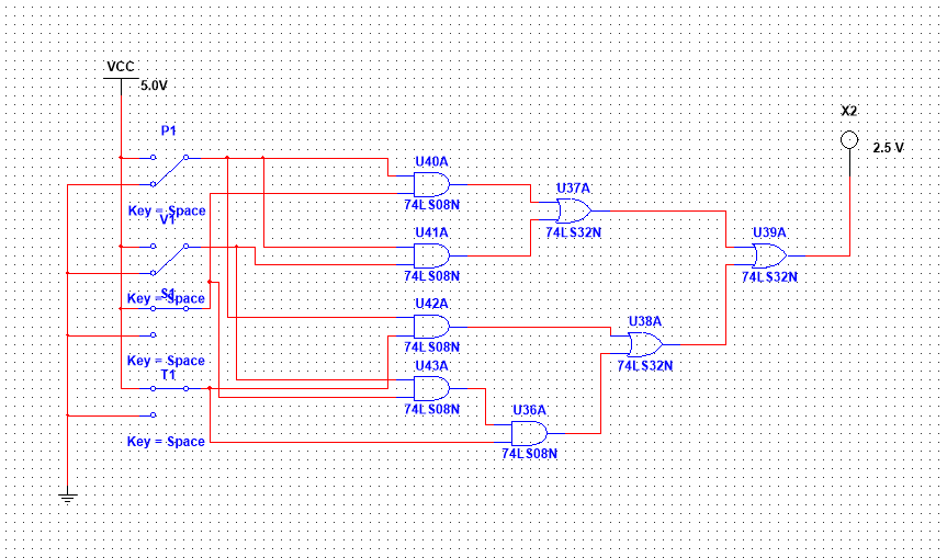
The circuit shown is not in bus form, because it does not require as many wires. The resistor is not present in the Multisim example here but it is used in the actual breadboarding of the circuit so that the LED does not explode. The circuit requires 5 AND gates and 3 OR gates, meaning that 2 AND chips (08) and 1 OR chip (32) will be needed. Each 08 and 32 chip contains 4 gates, meaning that if we need a total of 5 08 gates, then we will need 2 08 chips. 3<4 so only 1 32 chip is required.
The simplified circuit contained 4 less inverter gates (none were needed), 19 less AND gates, and 4 less OR gates. This makes it easier to build the circuit because you won't need to use as many chips or wires, so the final product will be more organized and mistakes will be easier to trace. The un-simplified is way more complicated than it needs to be and time consuming.
The simplified circuit contained 4 less inverter gates (none were needed), 19 less AND gates, and 4 less OR gates. This makes it easier to build the circuit because you won't need to use as many chips or wires, so the final product will be more organized and mistakes will be easier to trace. The un-simplified is way more complicated than it needs to be and time consuming.
Bill of Materials

This table shows the materials that will be needed to build the circuit and how many of each. The wires are a rough estimate, but you will probably need a lot.
Bread-Boarding
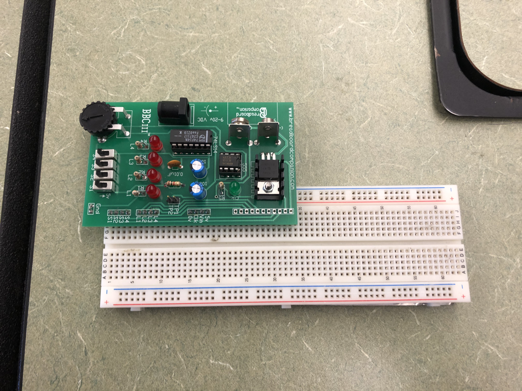
This is a picture of the breadboard and circuit companion before any wires or chips have been incorporated.
|

This shows the IC chips with wires set up to power and ground each chip and to bridge the positive and negative buses.
|

Here is a picture of the final product after mistakes have been fixed and the circuit has been successful!
|
My first breadboarding experience wasn’t too bad. I wired the circuit pretty quickly, and I was one of the first to finish, but I made a mistake with the placement of the resistor and LED at the end, when I connected a wire from the final output and then to the resistor rather than directly to the resistor. The project reinforced the skills that I had learned from the practice circuit, and I feel like I have a better understanding now. I was constantly checking the wires to make sure that they went to the right places and that they were all secure before testing to avoid any problems. I wish that I could have had time to color code more of the wires but it would have taken too long to clip and trim all of those wires.
Conclusion
This project has allowed me to practice with all aspects of circuits; from truth tables, to expressions, to Boolean algebra, to Multisim, and finally to the physical building of the circuit. I have learned the process of creating a simple circuit and how important it is to complete each step to the full extent and correctly. The project shows the importance of attention to detail and precision, because it’s very easy to place a wire in the wrong spot when breadboarding or even when building the circuit on Multisim. You’re most likely to be successful if you remain organized and do things such as color-code the wires. The basic process of going from a problem statement to a finished circuit begins with a truth table, which is created by looking at what you want the results of the circuit to be. Then you turn the “1” outputs of the truth table into your un-simplified expression, and if you want to waste time, you can build that circuit electronically (on Multisim). Then, you use Boolean algebra to reduce the circuit into a simplified version. This is the circuit that you will actually build and test once you have figured out how many chips, wires, and other materials are needed. Boolean algebra is extremely important because it consists of rules that can be followed in order to simplify a circuit so that it is not extremely complicated to wire and also to save money when manufacturing the circuit.
