Define the Problem

The objective of this project is to create a combination of three simple machines to flip a light switch on and off. The mechanical advantage must be greater than 1 and the effort force must be applied by one person.

Generate Concepts
Brainstorming Ideas:


Develop a Solution

Construct and Test Prototype

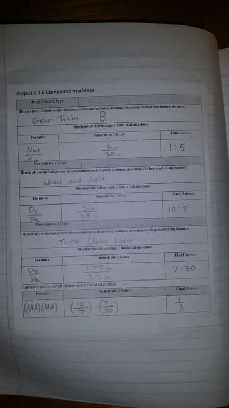
This is the gear train that was composed of a three gears including an idle gear. The gear ratio was 1:5.
|

This is a close-up of the wheel and axle. The mechanical advantage was 10:7 or approximately 1.43.

Here is the third class lever. The mechanical advantage was a horendous 7:30 or about 0.23.
|
Evaluate Solution
Throughout the building stage of the project, we had to make a lot of modifications. We had to play it by ear when setting up the gear train, mostly because we had to get it set in the right spot so that the lever would be lined up with the light switch. We then realized that the belt wasn't tight enough so we had to add another gear off to the side to increase the tension in the belt, hoping that this would fix our problem of the belt skipping when we turned the wheel. This helped a bit but then we tried to add more support to the back side of all of the axles. At this point, Mrs. Zienty reminded us to use the little 3-piece black things on either side of the hole that we put the axle into. Once we did this, our problem was solved. We still had a problem with the lever though; it didn't work exactly how we'd wanted it to. It required too much force to flick the light switch with a small movement so we had to result to bringing the lever all the way around and using the momentum to hit the switch. This was not the result that we expected, we thought it would have taken much less to flip a simple light switch.
Our actual results were similar to our calculated mechanical advantage because the ideal and actual mechanical advantage were both less than one. We obviously did not pass the test of a mechanical advantage greater than one, but at least our results were similar to that of our calculations. It definitely seemed like it was harder than it should have been to turn the wheel and to get the lever to work. But the actual mechanical advantage also takes into account friction and other natural factors that the calculated ideal mechanical advantage does not.
Our actual results were similar to our calculated mechanical advantage because the ideal and actual mechanical advantage were both less than one. We obviously did not pass the test of a mechanical advantage greater than one, but at least our results were similar to that of our calculations. It definitely seemed like it was harder than it should have been to turn the wheel and to get the lever to work. But the actual mechanical advantage also takes into account friction and other natural factors that the calculated ideal mechanical advantage does not.
Present a Solution

Silas and Kevin are brainstorming possible ideas.
|
We finished the basic foundation for our contraption but hadn't yet added the essential simple machines.
|

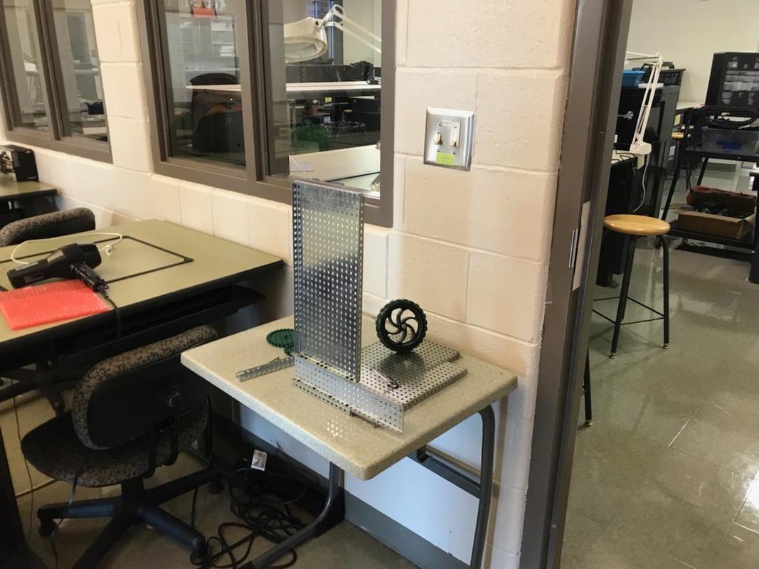
Here we have finished constructing after fixing and replacing and experimenting with many different parts.
|
| compoundmachine.3gp |
The biggest problem that we had with the VEX parts was that the gears were plastic. Because of the force that we had to apply to the wheel, the axles would turn the gear but the gear would resist and it caused some of the square holes in the center of the gears to become circular. We also did not exactly know all of the VEX parts that we available and what they could be used for. I know for me personally it has been about three years since I learned how to build things with VEX and I sort of forgot everything. When we decided that we were going to attach the lever to the top gear of the gear train, we didn't really have any idea of how we would do that, so we just had to experiment with different things and eventually we decided on attaching it to a bigger gear and adding it to the end of the axle because that was the only type of piece whose holes matched with the lever. I do think that it was a good experience because some things are coming back to me from 7th grade and I feel more confident in building with VEX now.
Conclusion
1. The gear train was the easiest because there were only two gears involved in the calculations and it was just the number of teeth of the top gear over the number of teeth of the driver.
2. The third class lever was the hardest to calculate because the fulcrum and the effort were in the same location and the distance had to be measured as well.
3. For every value of input, you will get about 1/4 of that value output. Our calculations show that for every input you will get 1/3 of that value for the output, but if you take into account friction then the ratio will go down to at least 1:4.
4. We could have had a counterweight on the lever to balance it out and found another way of attaching it. We could also decrease the diameter of the axle in the wheel and axle system. Any of these things would improve the overall mechanical advantage and therefor make it more efficient.
